"Ugly Duck" coaxial 1/4 wave dipoles for FM
easy, inexpensive, and better than expected performance
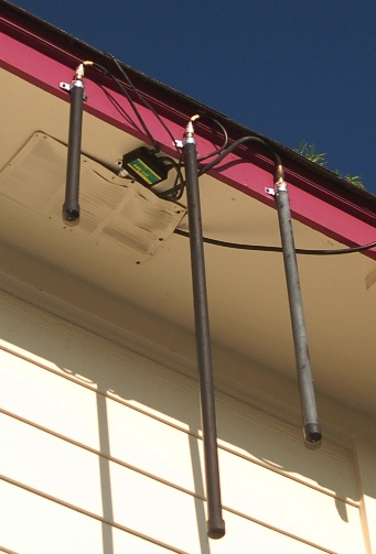
Author's 70cm, 2m, and 220 Mhz dipole collection at 17 feet up on a second story eave hanging inverted.
The diplexed 70cm and 2 meter ducks (left and middle) were retired in Feb of 2026 and replaced with a dual-band groundplane.
The 220 Mhz duck remains in service today on the base Alinco 220 rig.
By Steve Culp W5SDC
With the advent of linking amateur radio directly to the internet with Voice over IP technology, more and more HAMs are discovering and using the power
of this advancement to link low power, limited distance radios and antennas to repeater systems and conferences all over the world. Good amateur practice and FCC rules
dictate that our first responsibility is to always establish communications using the lowest and least disruptive resources possible, therefore; a small, vertical quarter wave FM dipole antenna
serves this purpose very well. Not only for link radios, but for everyday general purpose use also. And quite nicely. The simple coaxial dipole is certainly not a new invention; however, it is an antenna that always
seems to get the job done in an elementary and effective way. After all, the dipole has been and always will be in both the present and ancient roots of amateur radio.
I pondered some ideas that I had found online from John, W6NBC that had home brewed a coaxial 1/4 wave FM antenna using a metal
tube from an old floor lamp with the coax passing through the middle with the shield soldered to the tube. I also saw a design using copper tubing on smaller coax with
the shield tied to the tubing. I decided to try to emulate these designs using a piece of LMR 400 coax that I had in stock. I cut a portion of LMR to 1.3m 1/4 wave proportion and tuned it for the 220 band
since I had already stuck a 144/70 cm mobile antenna up on the roof to restore operation on those bands and was anxious to get a 220 link radio on the air for my RasPi AllStar Node 48133. I was so impressed by how well the first Ugly Duck performed on 220 that
I decided to build one for 2m and 70 cm to diplex together on the only coax run that I had left to the back two story corner of the shack. More on how the Ugly Duck got it's nickname later.
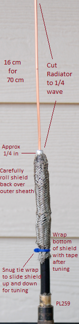 70cm Version
| Band | 1/4 wave radiator |
2 m | 49 cm |
220 | 32 cm |
70 cm | 16 cm |
As seen at Wikipedia
Transmission pattern illustrates why inverted operation works just fine.
A perfect specimen will produce 1.76 dBi of gain.
To get started, simply cut a piece of LMR 400 to 2x the quarter wavelength of the desired band plus a few inches to make sure that you have
enough distance on the bottom to slide the shield up and down for tuning and the addition of a Pl 258 or 259 connector if desired.
Without damaging the shield, carefully strip off the outer insulation of the coax to approximately 1/2 inch longer than
the length of the radiator that you require. Using both hands, gently push the shield toward the remaining coax sheath
so that it will compress and start to bulge to a diameter larger than the full outer size of the coax. Carefully roll the shield
inside out over the outer insulation leaving the center insulation and radiator exposed. The foil shield over the center conductor's insulator and the braid that you rolled back will form a tuning
capacitor that can be slid up and down to tune to the desired frequency and also eliminates the need for a ground plane.
If you desire, you can snug the
shield down with a tie wrap at this time. Note: Not trimming the tie wrap will leave you a "handle" to use while tuning as touching braid while tuning will
throw your readings off. A few "wild hairs" in the braid after fold back are OK as long as they are not shorted to the center conductor. Just trim them back with a pair of small scissors.
Next, strip the center conductor insulation off leaving approx 1/8 to 1/4 in above from where the shield folds back. Now the radiator
can be cut to match your desired 1/4 wavelength. Cut the exposed portion of the center conductor to exactly 1/4 wave measuring from the
stub to the end of the radiator. Install your PL-258 or 259 at the bottom and you will be ready to check it for shorts with an Ohm meter and then to tune her up simply by sliding the shield tube up or down. If you are creating a 70cm version, then you
will find yourself compressing the braided tube upward and stretching it downward for higher frequency models. After your exact tune, tighten the
tie wrap and trim all excess from it. Careful, the shield portion radiates and can bite you during tuning. Touching it will also throw off your SWR measurements. Taping the shield tube in place at the bottom of the tie wrap after final tuning is highly recommended.
The assembly slides easily in to 3/4 inch Schedule 40 PVC which did not affect the tuning on any of the three flavors that I built. Caution: Use of grey PVC may throw your bench tuning off and increase SWR. A 3/4 in galvanized electrical conduit clamp makes it easy to mount the antenna radiator up or down. I don't see
any reason why just carving this out on the end of a piece of coax and clamping or stapling it in place a few inches below the radiative shield wouldn't make a dandy
attic antenna that would be easy to horizontally polarize, say across horizontal wood rafters for SSB and CW operations. I have a feeling that a six meter version, although a little bulky, just might be a downright decent antenna when the band is open. Note: My tuning experience revealed that this antenna can be tuned for optimal SWR on either but not both polarizations. Or, at least
it couldn't be on my test bench with my particular set of tuning tools and skill.
The antennas that I built were both the necessity of economics and invention using the LMR 400 that I already had on hand. My original intent was only to create an antenna
for my Alinco DR-235 AllStar Link radio on 223.700, but during testing I discovered many full quieting signals from local repeaters up to 20 miles away. Good signal reports
on 5 watt simplex transmissions as well as low SWR across the band. The 2m and 440 Mhz versions have similar performance as well and are both diplexed to a Yaesu FTM-400XDR Fusion rig for C4FM communications on RF to my local C4FM repeater. RF serves as a backup in case direct connection of the FTM-400 to
the internet via Wires-X is out of order.
When I was playing around with the 440 version shown in the picture above, I screwed the PL-259 onto a BNC adapter and popped the naked duck onto my Alinco
DJ-596 dual band talkie to compare 440 performance to the factory antenna. At sixteen inches high and non-inverted it blew the factory antenna away but it
sure made the HT look ugly. Hence the name: Ugly Duck. But in it's defense, I think that maybe a little heat shrink or PVC just might transform it into a beautiful
swan for your local communications and budget.
Get off your dummy load and start your Ugly Duck farm today.
73
|
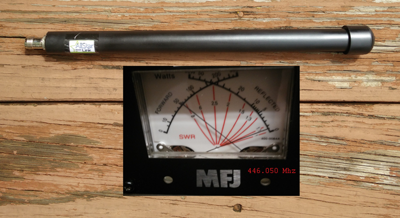 Custom tuned link version for AllStar Node 45933 SWR@ 5 watts 1:1.05
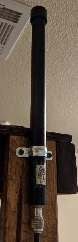 440 link installation at amateur station K5TMT
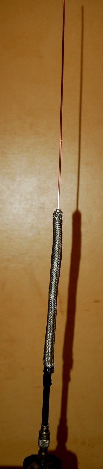 My very first build as seen on the tuning bench. Designed for 220 Mhz FM operation. Taped after final tuning and PVC ready. I was able to hit all local repeaters from the tuning bench. No ground plane required is another big plus.